Experimental Analysis of the Hydraulic Performance of Filtering Cartridges in Drinking Water Networks


1
Department of Civil Engineering, Università degli Studi di Salerno, 84084 Fisciano, Italy
2
Department of Civil and Mechanical Engineering, Università di Cassino e del Lazio Meridionale, 03043 Cassino, Italy
*
Author to whom correspondence should be addressed.
Water 2018, 10(5), 629; https://doi.org/10.3390/w10050629
Submission received: 4 April 2018
/
Revised: 7 May 2018
/
Accepted: 8 May 2018
/
Published: 11 May 2018
(This article belongs to the Special Issue Hydrology, Water Resources Management and Protection of the Marine Environment–Selected Papers from the 15th International Conference on Environmental Science And Technology (CEST2017))
Abstract
:Liquid treatment processes have been assuming increasing importance in recent decades with the progressive industrialization to ensure public health security for drinking water or to prevent economic damage when safeguarding important production processes. Major investments have been devoted to the research, study, and design of innovative products that are able to respond to the demands of the market, which currently offer several solutions, among which filtration treatment still represents a major one. This work focuses, in particular, on filtration of drinking water with filter cartridges, with the aim to test their hydraulic performance and, particularly, to evaluate the head losses that they produce when introduced into a hydraulic system. The local pressure drops, in fact, may compromise hydraulic plants already characterized by low pressures. What is more, this condition is increasingly likely in supplying networks due to the coexistence of several factors, such as water losses due to failures and inefficient maintenance, severe and prolonged droughts, and increased water demand related to social and economic development. In these systems, the insertion of filtration cartridges can make the pressure levels fall below the minimum limit recommended to ensure the smooth operation of domestic devices. More in detail, in the present study the behavior of seven different commercial filter cartridges was analyzed through a set of experiments conducted in a pilot circuit at the Laboratory of Environmental and Maritime Hydraulics (LIDAM), University of Salerno. These tests have been performed in different operating conditions, collecting pressure data through various pressure gauges. The analysis proved that for common values of operating flow rates in domestic plants the pressure drops in the filter can be of the order of some meters and provided some useful information for the choice of the proper cartridge in low-pressure distribution systems.
1. Introduction
Nowadays, progressive industrialization and uncontrolled social and economic development, with consequent pollution and environmental degradation, have made water treatment absolutely necessary for many uses (e.g., [1,2,3]). Treatment processes have two important purposes: (1) to make possible the use of water that otherwise would not fit the required specific purpose, which may be a human, domestic, industrial, or agricultural one [4,5,6]; and (2) to make the water, which was previously polluted by specific processes and operations, safe (e.g., [7,8]). Specifically, the progressive deterioration of water quality, due to various contaminating processes, has made necessary in most of the cases a proper treatment of water before human utilization. Among the different water treatment techniques, e.g., pre-chlorination, coagulation and flocculation, sedimentation, disinfection, etc., filtration still represents the main solution [9,10]. Almost all the domestic apparatuses that make use of water are equipped with internal filtration elements or are installed with proper filtration systems. Increasingly, efficient and innovative water filtration systems have been adopted in recent years [11,12].
Focusing on drinking water filtration, the analysis of the literature shows very few studies on the hydraulic analysis of filtering cartridges. Besides, these works are usually focused on different features of the filtering cartridges, such as water quality aspects or efficiency of the filtration process, or on specific topics, such as on the removal of specific substances from drinking water, or refer only to wire-wound cartridges. It is worth mentioning a comprehensive guide concerning filtration techniques, systems, and their applications proposed by Sutherland [13]. More recently, a book dedicated to wire-wound cartridges was published by Kanade and Bhattacharya [14]. Kanade and co-workers [15] defined the relation between spinning suction pressure and performance parameters of wire-wound filters. To this aim, tested cartridges were produced by means of an electronically controlled precision filter winder [16]. In [17], the efficacy of common water filtration and purification systems bought by consumers and used at home in the removal of cyanotoxins from water was assessed. Among the others, the use of tested carbon filters provided protection against human exposure to cyanotoxin but in conjunction with the application of water treatment methodologies utilized in water treatment facilities. Tomaszewska and co-workers [18] proposed a polypropylene cartridge filter for solid particles retention and arsenic removal.
The present study is focused, instead, on the effects, in terms of head losses, produced by the installation of a filter cartridge in a drinking water plant. These effects, in fact, are not negligible and may determine pressure values not compatible with those required for a proper functioning of some electro-mechanical elements present in domestic water systems (dishwashers, washing machines, boilers, etc.). As an example, considering a plant with an inflow pressure of about 1 bar, the installation of a filtering cartridge will produce a pressure loss of the order of several tenths of bar; thus, the operating pressures will fall below the minimum limit of 0.8 bar recommended by the domestic equipment manufacturers for their smooth functioning.
In view of a limited research investigation on the matter, an ad-hoc pilot circuit was designed and built at the Laboratory of Environmental and Maritime Hydraulics (LIDAM), University of Salerno, Italy, to perform experiments aimed at giving more information about the head losses produced by the most common filter cartridges. Past experimental investigations carried out on the circuit focused on the behavior of string-wound cartridges when artificially clogged with fine sand [19] and fine gravel [20]. Starting from the work presented in [21], this study analyzes and compares, instead, the hydraulic performance of seven different commercially popular filter cartridges.
During the experiments, the pressures were measured both in the original system (i.e., in the absence of cartridges) and in the presence of each of the seven cartridges with different operating scenarios, in order to evaluate the local losses produced by each filter cartridge. The results provide useful information for the selection of the proper cartridge in low-pressure distribution systems, a choice that will be clearly determined also by the specific water quality and the consequent required treatment.
2. Materials and Methods
In this section, first the different filtration modalities corresponding to the seven selected cartridges for the analysis are briefly described. The pilot circuit designed and built in the laboratory is then presented, along with the related components, the instrumentation, and the operating conditions of the performed experiments.
2.1. Filtration Cartridge Systems
The filtration cartridge systems available on the market can be grouped in two distinct categories:
Several different types of filter cartridges are commercially available, with their own characteristics and, therefore, more or less suitable for the filtration of specific fluids. Eligibility is recognizable in relation to specific factors: nature of the liquid to be treated, particle size, filtration efficiency, permeability of the filter material, pressure loss, chemical compatibility, thermal stability, cost/benefit ratio, and maintenance.
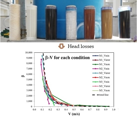
Among the available cartridges, only the seven most popular ones (illustrated, in the order, in Figure 1) have been considered in this study:
- wire-wound polyester filter,
- nylon mesh filter,
- granular activated carbon filters,
- filter cartridge with crystal polyphosphate,
- cationic resin filter cartridge,
- anionic resin filter cartridge,
- mixed-bed resin filter cartridge.
All the cartridges tested in the laboratory in this work were produced by “Acqua Brevetti 95 S.r.l.”, Mestrino (PD), Italy. Some tests have been repeated also for cartridges produced by “Idrocosmotek, Fimi S.p.A.”, Izano (CR), giving very similar results. In any case, since their characteristics agree with the standards of most brands on the market, results can be considered generalizable to other commercial cartridges. Further experiments are to be performed with this aim.
Each cartridge was analyzed in the function performed when adopted in a given plant, evaluating the behavior in the different operating conditions of the pilot circuit.
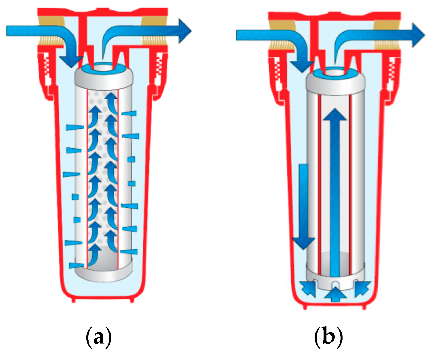
The transit of the fluid in the cartridge, during which the treatment phase takes place, can occur essentially with two different modes:
- radial flux: The fluid flows through the cartridge with a side entrance (lateral inflow), the solid particles deposit in the filter, and, once water reaches the central part, it flows upward (outflow) through the duct created in the inner core (Figure 2a);
- direct/inverse flux: The fluid motion occurs with an input from the bottom and outflow from the top (Figure 2b).
An important parameter to define in order to characterize the filter cartridge is the pore size nominal rating or nominal filtration of a cartridge [13], defined as the pore size at which particles of a given size will be retained with efficiency below 100%. It refers to the capability of the filter to capture particles by the process of absorption, which depends on the size of the filter holes [14]. It is measured in μm, and it is linked to the efficiency of the same expressed in percentage (e.g., an efficiency of 80% with pore size nominal rating of 50 μm means that 80% of the suspended solid particles dispersed in water having a nominal size greater than 50 μm are retained by the filtering septum during their transit through it).
The seven above mentioned types of filter cartridges are described in detail in what follows.
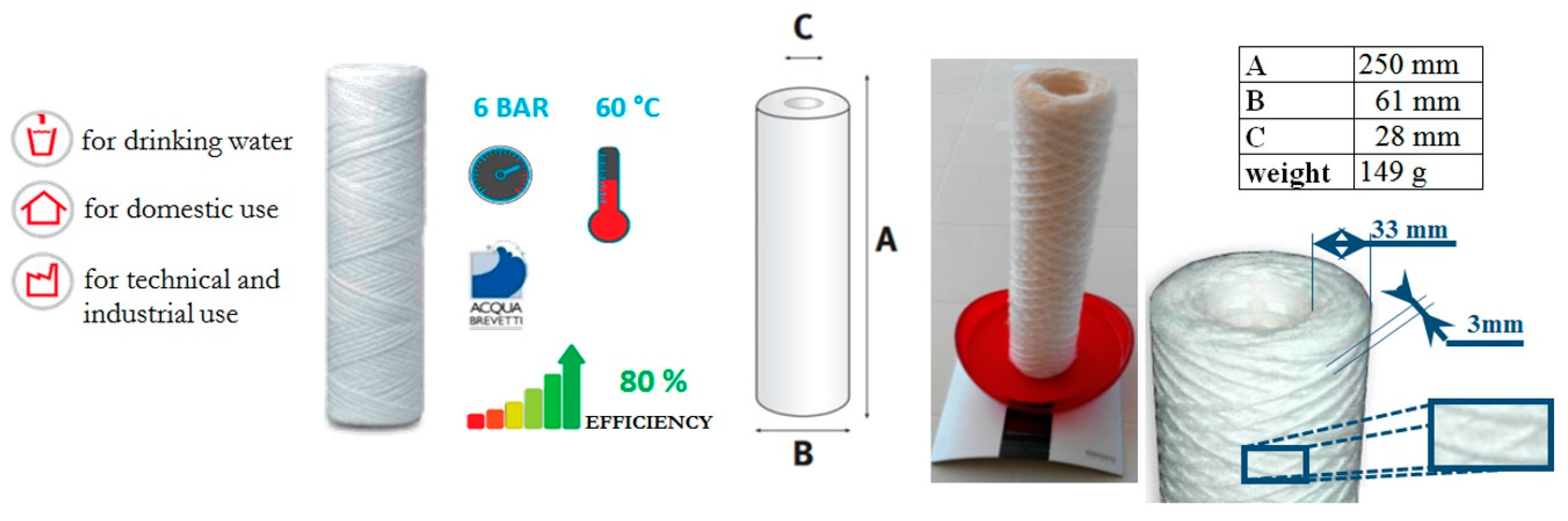
2.1.1. Wire-Wound Polyester Filter Cartridge
A wire-wound filter cartridge works for mechanical filtration [19]. It is produced by winding a wire on a central support core, both made of pure polypropylene, very tenacious and non-toxic, that makes it suitable also for the treatment of drinking water [15]. The one adopted here is of the type in Figure 3, in which size, weight and efficiency are also reported. The filtering set has a particular honeycomb uniform texture, with pore size nominal rating of 50 μm.
The fluid motion occurs with mode 1 (Figure 2a). When the filter is completely clogged, to restore the filtration system in its early ideal conditions, the cartridge has to be replaced, since a wash would not allow the complete cleaning of the septum, being the solid particles retained in the filter matrix and not only on the external surface.
2.1.2. Nylon Mesh Filter Cartridge
The nylon mesh filter cartridge works for mechanical filtration [22,23]. The filtration process is, in this case, direct interception-type: when the flow reaches the filter, this stops particles of diameter smaller than that of its pores. Particles may be also caught from the filter by bridge effect if they are smaller but positioned “sideways” with respect to a pore, or if two or more particles hit a pore at the same time, or if another particle partially occludes a pore, or if surface interactions arise, making small particles adhere to the inner surface of the pores.
The filter is made by weaving a square mesh of polyester wires, which are tough, resilient to bending, and resistant to chemical and physical agents. Its structure, with a smooth surface, allows a uniform flow, minimizing the risk of occlusion and ensuring an accurate filtering capacity with minimum head loss.
The one chosen for this study is of the type in Figure 4, in which also a zoom of the core and nylon grid are shown. The pore size nominal rating is 150 μm.
The fluid motion occurs with mode 1 (Figure 2a). This cartridge is simple to use, and proper maintenance allows prolonged use in time with constant efficiency. The suspended and settleable solid particles carried by the flowing water stop in this case on the outer surface of the filter, which may be easily cleaned by means of a simple washing operation. The material is of non-toxic type, and the performed filtering action is sufficient to make the outflow water suitable for human consumption without the need for further treatment.
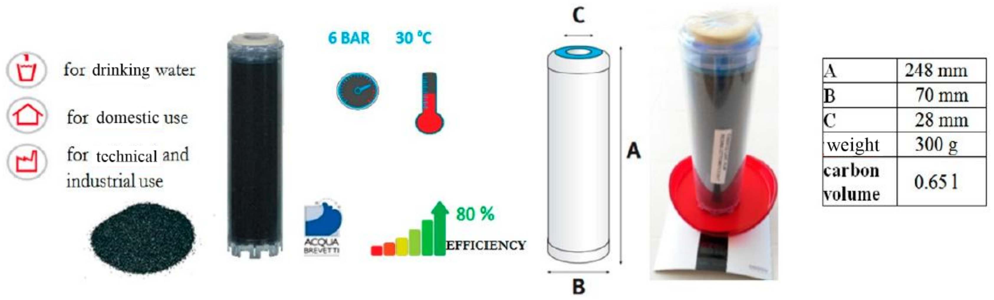
2.1.3. Granular Activated Carbon Filter Cartridge
A granular activated carbon filter cartridge works for water treatment, because it removes halogenated organic substances, such as trihalomethanes and other DBP (disinfection by-products), pesticides, herbicides, triazines, chlorine, and other substances that impart unpleasant odors and flavors, and color [24,25].
Activated carbon mainly contains amorphous carbon, which has a highly porous structure and a very large specific area, and it is, therefore, able to retain many molecules of other substances, i.e., it has high adsorbent capacity. The material is non-toxic, although for the treatment of drinking water a further disinfection treatment is recommended to remove or disable any eventual pathogenic microorganisms.
The granular-activated carbon filter cartridge chosen for this study is of the type in Figure 5, with pore size nominal rating 5 μm.
The fluid motion occurs with mode 1 (Figure 2b). After reaching the full saturation of the filter, the cartridge has to be replaced.
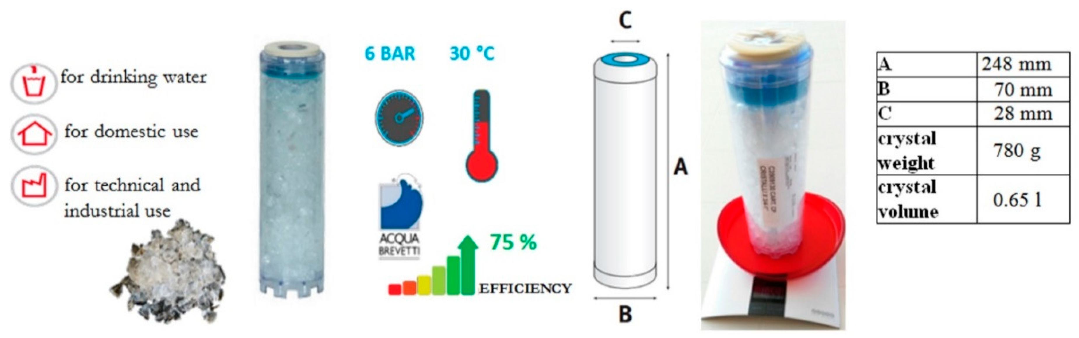
2.1.4. Filter Cartridge with Crystal Polyphosphate
A filter cartridge with polyphosphate works for water treatment, as it protects from the formation of incrustations deriving from limestone and corrosion in the hot and cold-water distribution lines [26]. The one adopted here is of the type in Figure 6.
Polyphosphates are salts obtained from polymerization by heating acid phosphates, and differ from one other in their degree of polymerization and structure.
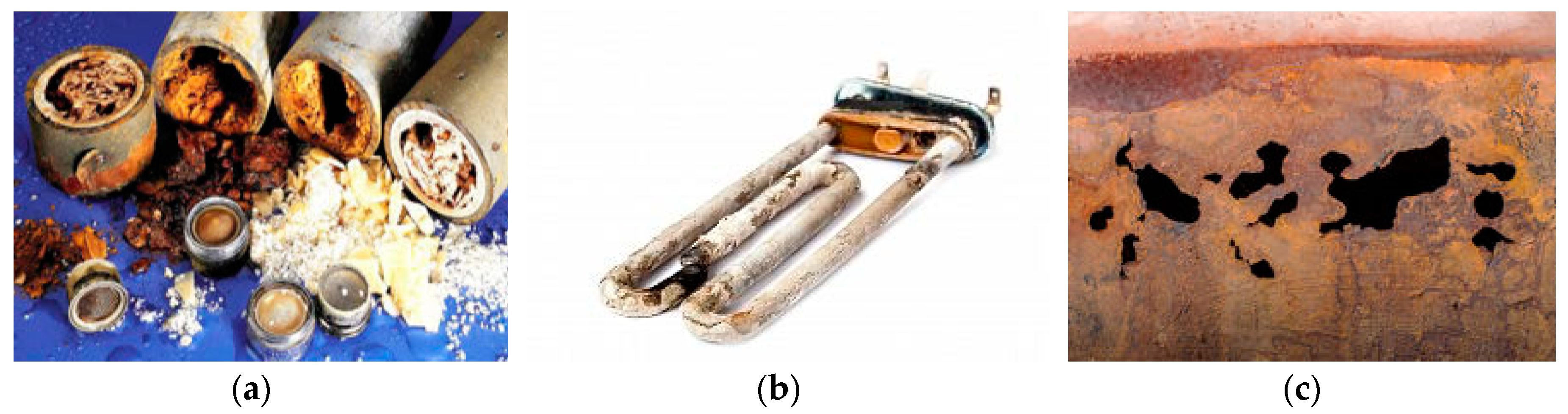
Limestone is due to the presence of calcium and magnesium salts dissolved in water as soluble bicarbonates, which, when heated, are transformed into insoluble carbonates and tend to stick in clusters of crystals. Over time they form deposits on the surfaces of tubes, coils, and tanks of hot water production plants (Figure 7a,b), causing malfunctioning, drastic drop in energy yield, and high running and maintenance costs. Plant safety filters are even prescribed by law for facilities of domestic hot water.
Corrosion may cause thinning and perforation of the wall pipes and alteration of the composition of water and its organoleptic properties. In fact, the rust flakes can be detached from the inner walls of the pipes as effect of the flow or temperature variations, carried by the water and deposit on the surfaces of other system components, also affecting their operation (Figure 7c).
The polyphosphate acts as an effective mean of protection against corrosion, forming a thin protective film on the surfaces of pipes, coils, and water heaters, thus providing a longer conservation in time of the treated components.
The treatment efficiency of this cartridge is the lowest (75%) of those analyzed here, while the pore size nominal rating is of the order of 20 μm.
The fluid motion occurs with mode 1 (Figure 2b). When the cartridge is exhausted, it must be replaced to ensure the filtration optimal conditions. The polyphosphate employed to treat drinking water needs to be appropriately dosed, not exceeding a certain concentration determined by the current legislation.
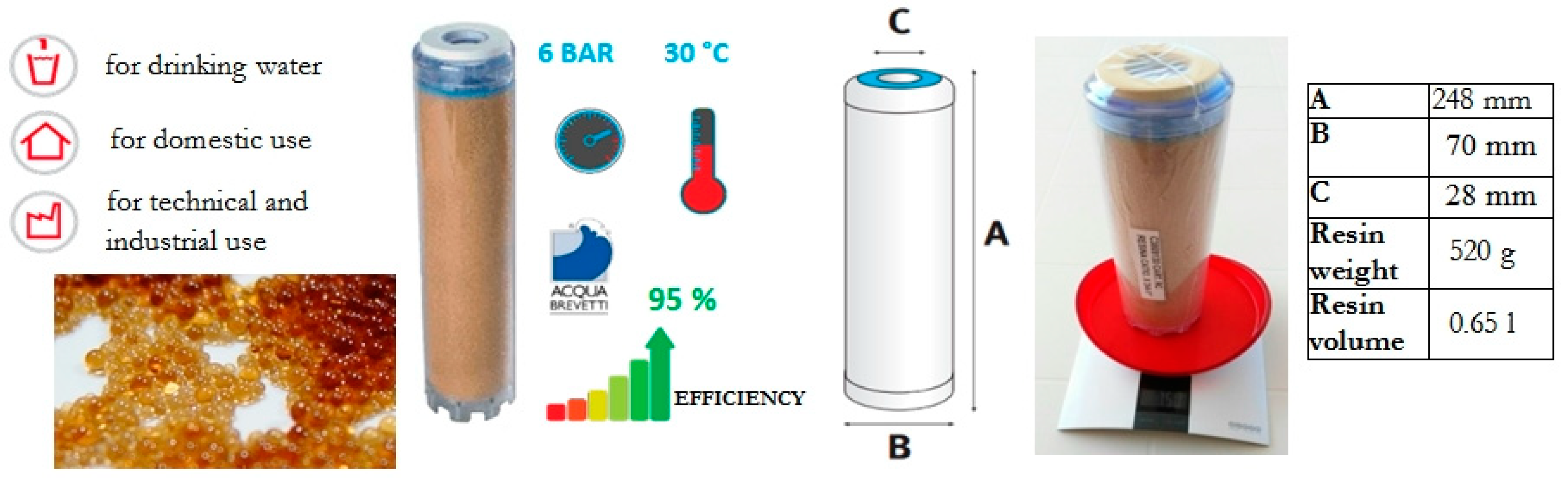
2.1.5. Cationic Resin Filter Cartridge
A filter cartridge in cationic resin falls into the category of cartridges for water treatment, as it softens the water, thus eliminating its hardness [29]. The one selected for the experiments is described in Figure 8.
The cationic resins are solid, non-soluble substances, specifically organic macromolecules formed from a crosslinked polymeric matrix with a large number of active functional groups, capable of interchange ions with a liquid, e.g., water. Cationic resins fix positive ions and anionic resins negative ions. The process consists, basically, of the substitution of calcium and magnesium ions in water, responsible for the scale formation, with sodium ions released from the resin. The resins are composed of small balls with a diameter generally between 0.3 and 1.2 mm.
The fluid motion occurs with mode 1 (Figure 2b). The pore size nominal rating is of the order of 40 μm. After reaching the full saturation of a resin, a regeneration phase is required, by means of which the resin, in contact with a specific substance, for example, sodium chloride, will release the calcium and magnesium ions reacquiring sodium ions. This resin is suitable for drinking water treatments if the treatment takes place within specific limits established by law.
2.1.6. Anionic Resin Filter Cartridge
A filter cartridge in anionic resin works for water treatment, as this resin is capable of implementing a reversible interchange of ions with the liquid. The one adopted here is described in Figure 9. The resin grains have diameter in the range 0.3 and 1.2 mm [29,30].
The objective is to reduce the presence of anionic mineral salts, such as those containing sulfate, nitrate, and chloride ions of the water, substituting these ions with hydroxyl ones released by the resin), thus reducing the possibility of compromising human and plant health.
High sulfate concentrations in drinking water can have a laxative effect if combined with calcium and magnesium or turn into hydrogen sulfide gas in the presence of bacteria, or be responsible for the system corrosion. The nitrate ions are harmless to human health, but they often turn into nitrites, which are toxic and can result in respiratory distress and even asphyxiation (blue disease). The chlorides dissolved in water increase its electrical conductivity and the fixed residue; in high concentrations, they can affect the water taste and flavor and cause pipe corrosion.
The fluid motion occurs with mode 1 (Figure 2b). The pore size nominal rating is of the order of 40 μm. The anionic resin cartridge can be used for domestic water treatments and for the production of drinking water with nitrate concentrations lower than 10 mg/L.
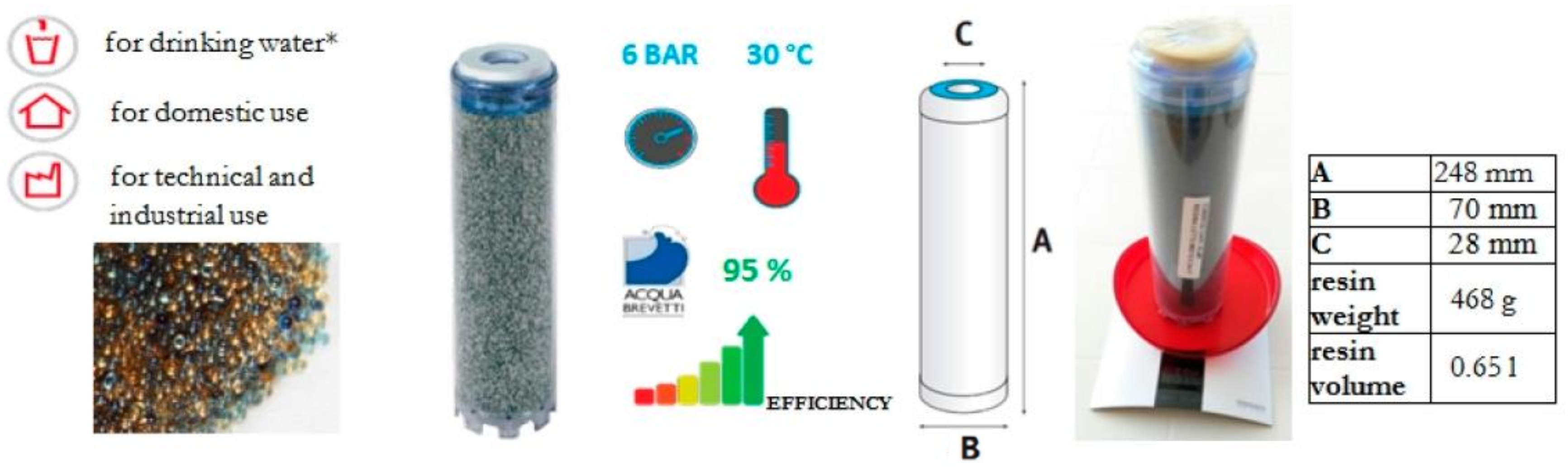
2.1.7. Mixed-Bed Resin Filter Cartridge
A mixed-bed resin filter cartridge works for water treatment, since it is a mixture of anionic and cationic resins that are able to remove simultaneously both the cations (exchanged with hydrogen ions) and the anions (exchanged with hydroxyl ions) from water [29,31]. In this work, the one described in Figure 10 has been adopted.
The fluid motion occurs with mode 1 (Figure 2b). This cartridge can be used for the production of demineralized water and for all uses requiring water free of salts. If suitably controlled, the treated water may be also used for human consumption.
2.2. Laboratory Setup
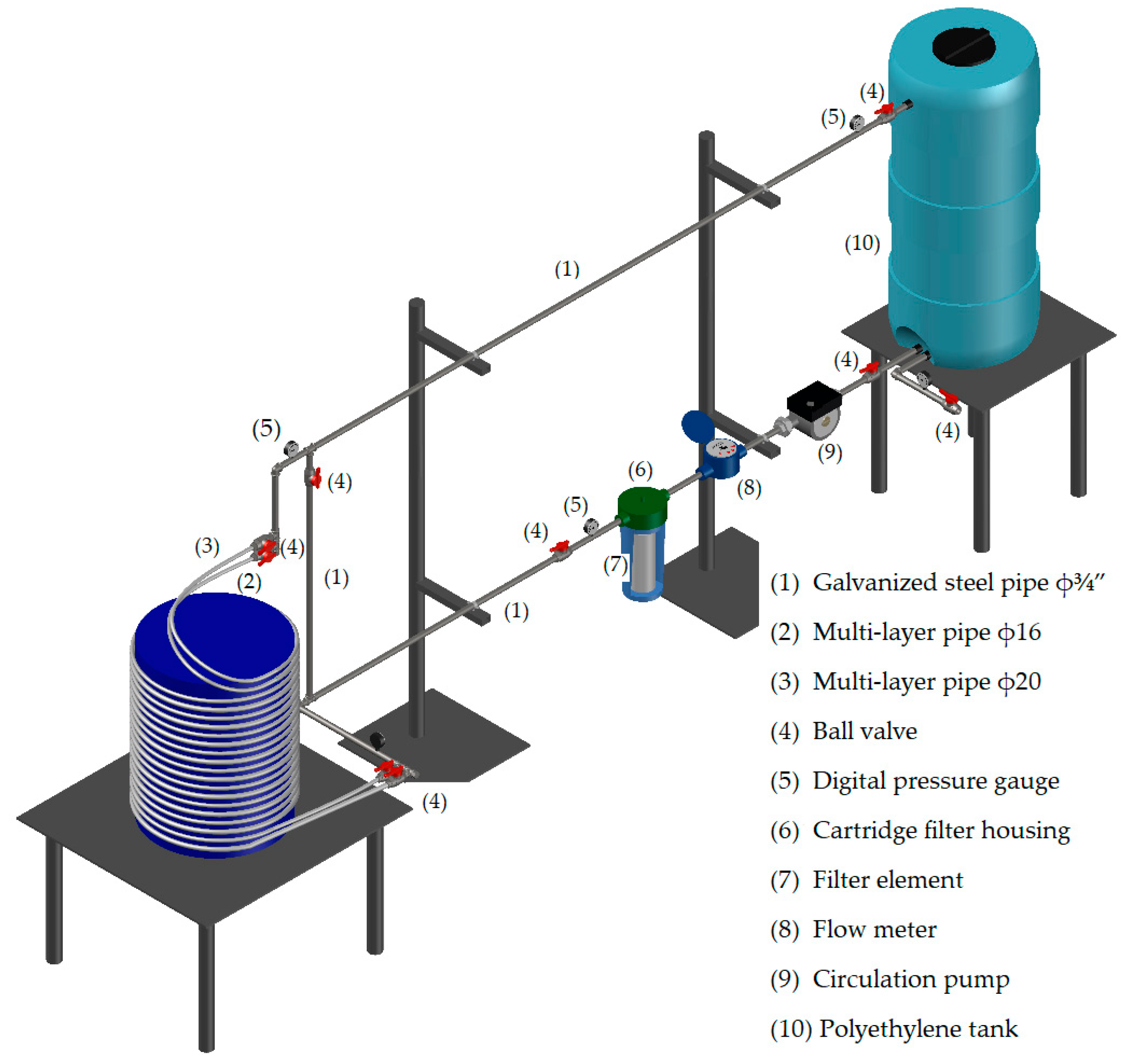
The hydraulic pilot circuit (Figure 11) designed and built in the LIDAM laboratory at University of Salerno was aimed at simulating a generic residential plant with a cartridge filtration system, so it was made of pipes with commercially popular materials and diameters. It consists essentially of [19]:
- a 300 L capacity polyethylene tank,
- an electronic circulation pump with maximum head equal to 6.9 m (model Evosta 40–70/130, flow rate range 0.4 ÷ 3.3 m3/h),
- a galvanized steel pipe with diameter ϕ¾” (internal diameter 20.9 mm) and length 7.05 m,
- a pipe in multi-layer material with diameter ϕ16 (internal diameter 12 mm) and length 25.00 m,
- a pipe in multi-layer material with diameter ϕ20 (internal diameter 16 mm) and length 25.00 m,
- a single-jet water meter,
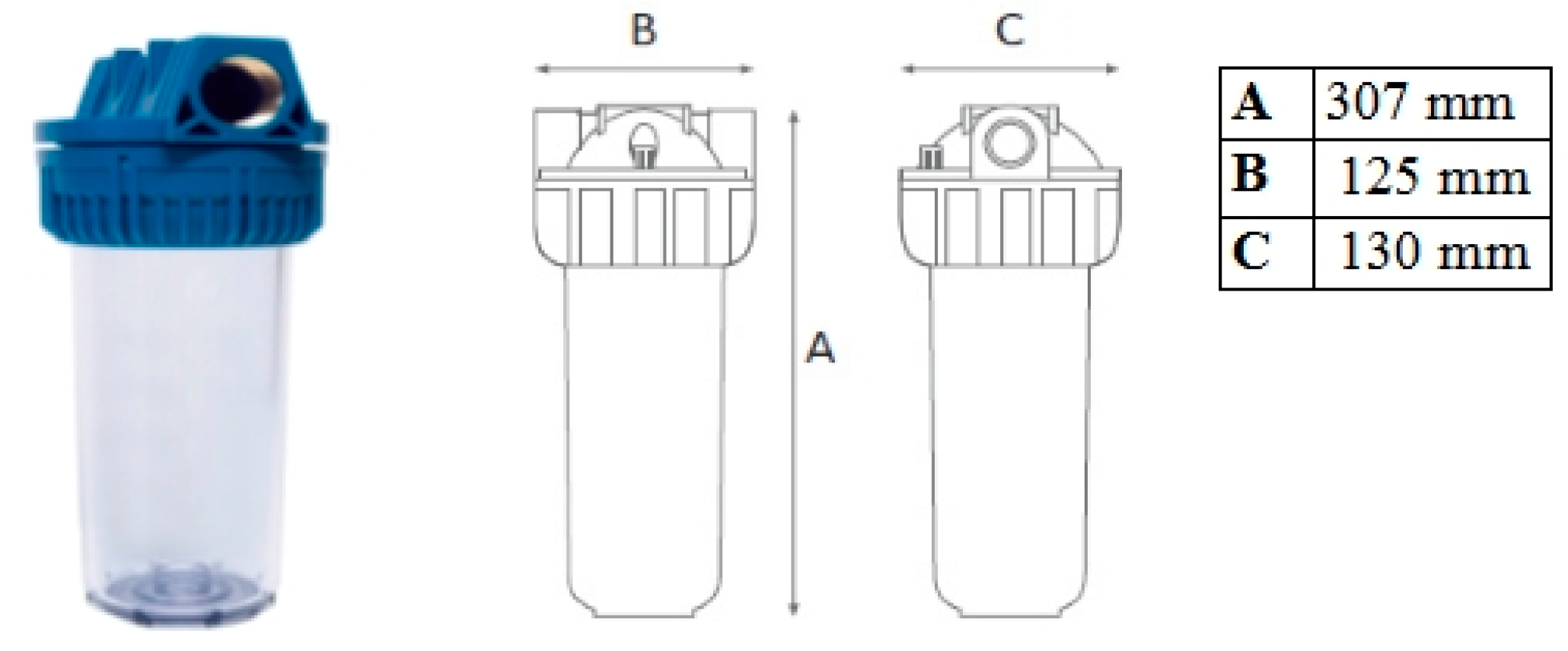
- a housing element (Figure 12) with interchangeable filter cartridges.
The two pipes in multi-layer material, with diameters ϕ16 and ϕ20, respectively (numbers 2 and 3 in Figure 11), are linked in parallel and used one at a time, thanks to seven ball valves posed along the circuit, which also regulate the flow rate. The analysis, in fact, has been conducted in different operating conditions for each of the analyzed cartridges, put from time to time in the proper container.
The cartridge container (model FC GREEN V/T, Figure 12), also produced by Acqua Brevetti 95 S.r.l. of Mestrino (PD), permits the accommodation of the different 9 ¾” filter cartridges here considered.
2.3. Experiments
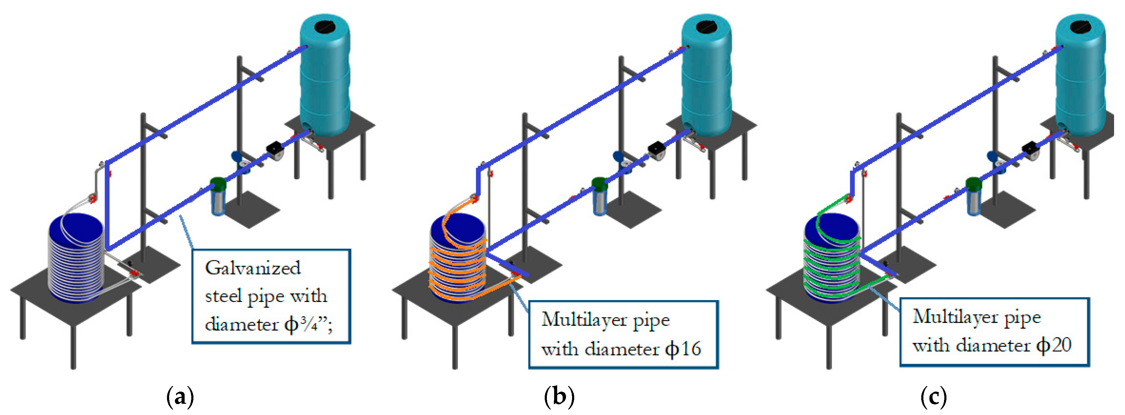
The circuit can be used, thanks to the system of valves and being the two pipes in multi-layer material (ϕ16 and ϕ20, respectively) linked in parallel, in different modes. Three scenarios are considered in the presented experiments (Figure 13):
- -
- Mode 1: bypass of the multi-layer pipes and use of the only short galvanized pipe of the circuit (blue one),
- -
- Mode 2: multi-layer pipe with diameter ϕ16 opened (blue and orange pipes),
- -
- Mode 3: multi-layer pipe with diameter ϕ20 opened (blue and green pipes).
In each circuit (modes 1, 2, and 3), experiments have been performed with three different values of discharge (Qmin-minimum, Qinter-intermediate, and Qmax-maximum), depending on the operating modes of the pump as well as on which filter cartridge (among those listed in the Section 2.1) was inserted in the plastic container (Figure 12).
When the circuit is operating, the pressure values in different properly selected detection points of the circuit are measured through digital pressure gauges (model Sino Instruments HX601) in order to calculate the head losses along the pipe. Concentrated head losses at the filter cartridges are measured, instead, through electronic differential manometers (model Digitron Engineering B.V. 2082P), positioned with the two detection points upstream and downstream of the cartridge, respectively (Figure 11). Each measurement has been performed three times in order to verify the repeatability of the experimental tests. Also, a flow meter by B Meters S.r.l. was installed between the pump and the filter housing. The accuracy of the measurements was ascertained prior in a single campaign of experimental tests, by comparing the readings obtained from the instruments with known values, alternatively detected. The flow meter was calibrated, for each pump speed and filter conditions, through a bucket or volumetric method, by diverting the flow to a bucket of known volume, measuring the time to fill it, and calculating the discharge as ratio of this volume to the filling time. The procedure was repeated three times in each case.
Before each test, digital pressure gauges were reset to zero in absence of water in the steel pipe, to match the atmospheric pressure value. In addition, for pressure gauges with readings lower than 0.2 bar, a comparison was made by reading the water levels at piezometers that were 2 m high and placed in the same locations thanks to the presence of four-way fittings [19].
3. Results and Discussion
Results of the experiments are summarized in Table 1 in terms of head losses ΔH (in m) as functions of corresponding discharges Q (in L/s) in the conditions of no filter cartridges (NF) and introducing one at a time the seven filter cartridges for the three different values of discharge and for the three operating conditions (modes 1, 2, and 3).
Discharges have been measured by volumetric flowmeters. The values of local head losses between the upstream and downstream sections of the filter holder are those calculated starting from the measured water level in the upstream tank (whose variations during the experiments have been tested to be considered neglectable) with the Hazen-Williams resistance formula and roughness coefficient 110 for the galvanized steel pipes and 150 for the multi-layer pipes, respectively. The values have been averaged starting from the acquisitions of the repeated tests.
In all the conditions for low values of discharges, the corresponding head losses increase significantly in a linear way. However, for most of the filters, once they exceed a threshold value of the discharge Q, the head loss keeps constant or grows more slowly.
The no filter (NF) condition represents for the circuit a sort of threshold case, with no concentrated pressure drop produced by the introduction of a filter cartridge in the plant [7].
Among the different cartridges, number 6 and 7 (anionic and mixed-bed resin filter cartridges, respectively) produce the highest head losses (discharge being equal), while the lowest are given by numbers 2 and 4 (nylon mesh and crystal polyphosphate filter cartridges, respectively). It is important to notice, though, how the values of discharge change as the pump adjusts its operating point.
In conclusion, for common values of operating flow rates in domestic plants, i.e., in the range 0.1–0.3 L/s, the pressure drops in the filter can even exceed the value of 5 m.
A generalization of these results, and a formula of the type of Equation (1) for the calculation of the local head loss produced by the filter cartridge in each scenario, have been sought:
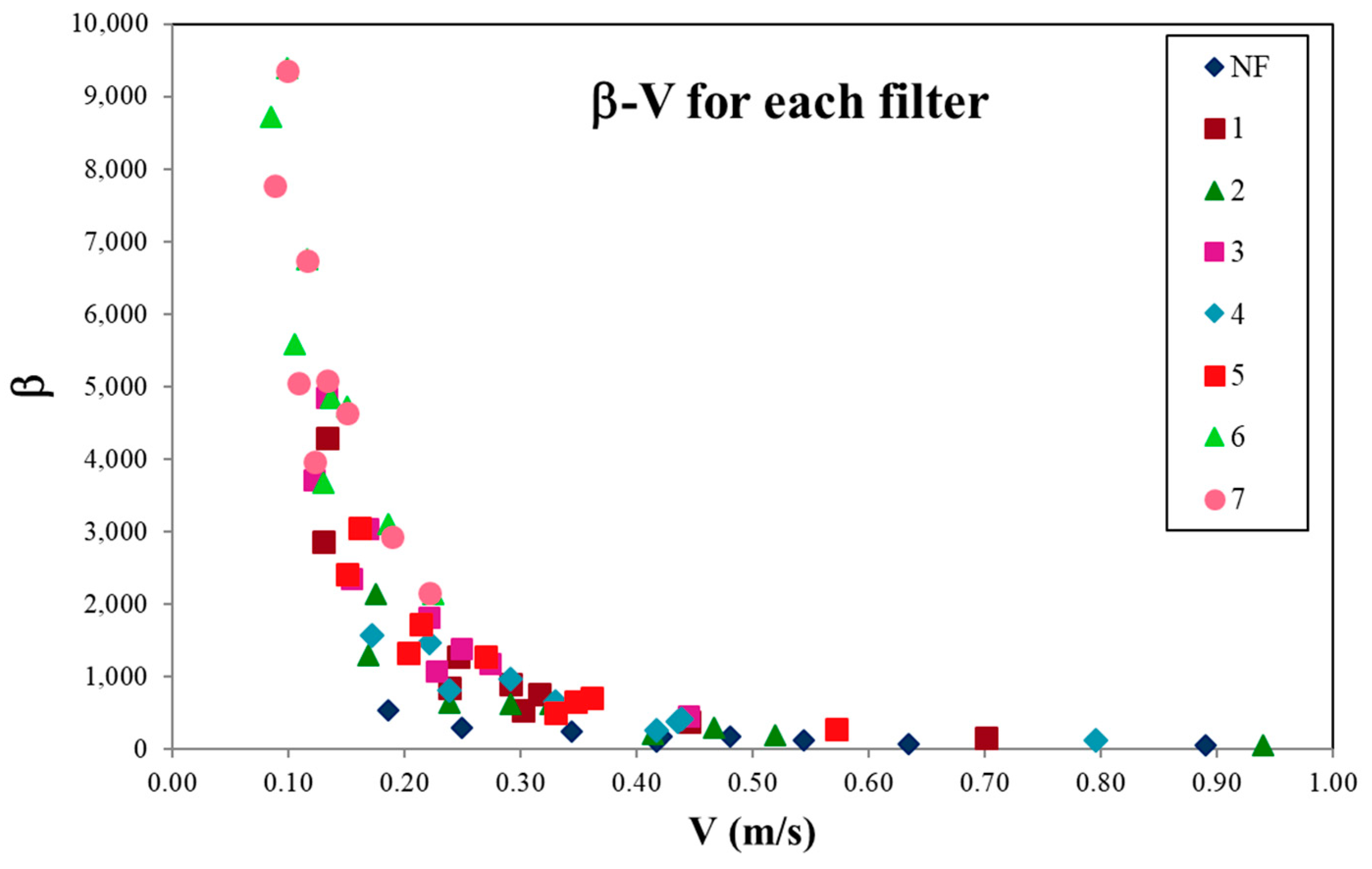
Starting from the pair values of discharges Q and the corresponding local head losses, first the corresponding mean velocities by the continuity equation and then the values of coefficient β in Equation (1) have been calculated. Results are reported in Table 2.
Also, the values of β have been plotted as function of the corresponding values of the mean velocity V in all the scenarios for each cartridge in Figure 14.
Three different trends can be distinguished for the analyzed cartridges:
- -
- Group 1: cartridges number 6 and 7 (Figure 15a), for which the values of head losses are high and up to , with a very steep trend curve;
- -
- Group 2: cartridges number 1, 3, and 5 (Figure 15b), for which the values of head losses are average and β lower than , with a less steep trend curve;
- -
- Group 3: cartridges number 2 and 4 (Figure 15c), for which the values of head losses are much lower and β less than , with trend curve characterized by a much lower slope.
The following averaged relations can be obtained from the trend curves for the three groups:
- -
- Group 1 (cartridges 6 and 7): ,
- -
- Group 2 (cartridges 1, 3 and 5): ,
- -
- Group 3 (cartridges 2 and 4): .
Although it is not possible to identify a physical reason for the classification of the filters in terms of their hydraulic response in the groups, it can be said that the different behaviors depend on the constructive features of the filter and on the materials and the modalities of the flow into the filter itself. The friction at the grain surface for the filters with solid particles, and, in general, the nominal size rating, seem to affect the produced head losses.
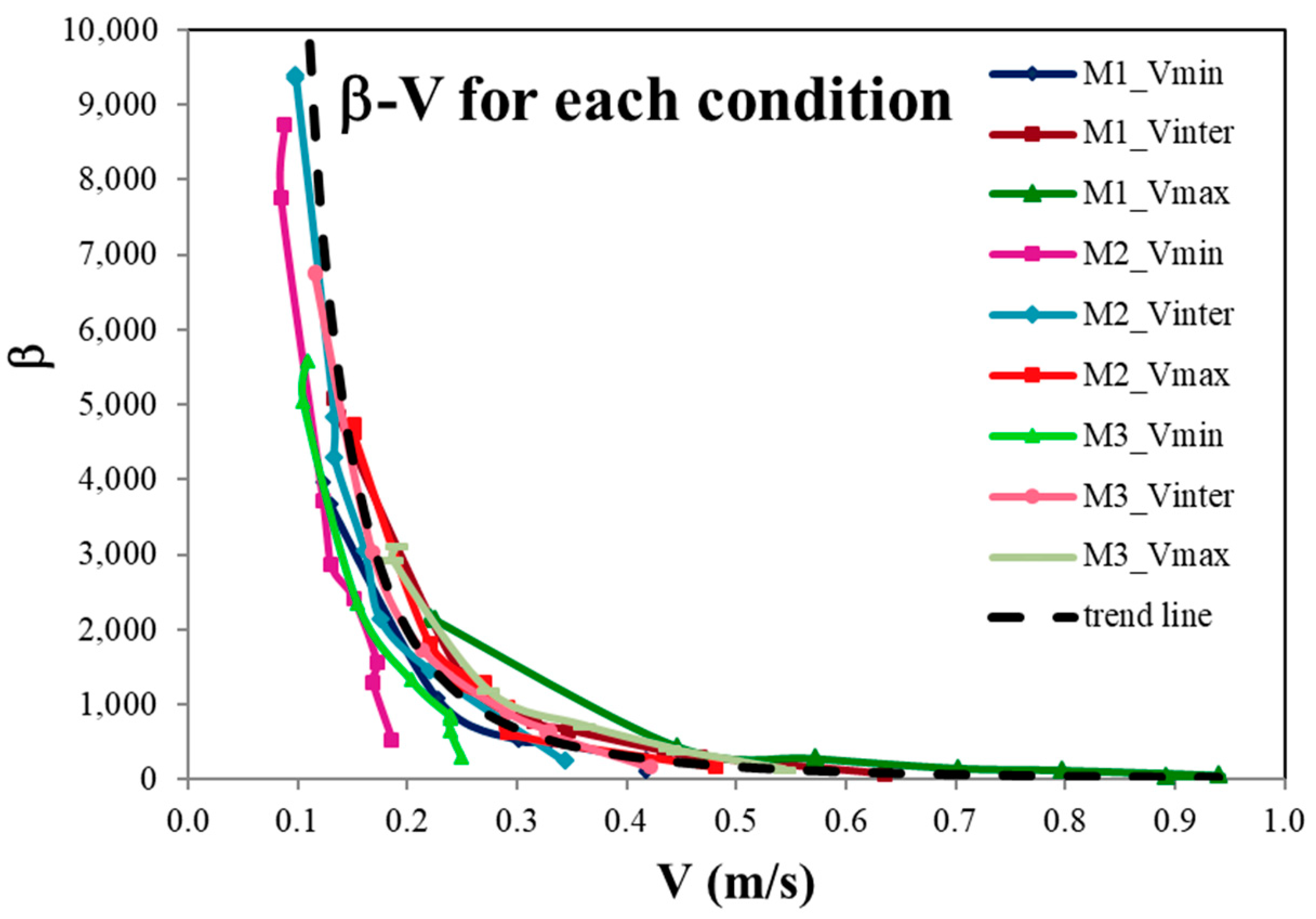
On the other side, more generally the results can also be represented for all the cartridges for each of the nine operating conditions (three velocities for each of the three modes).
Each curve for each operating condition (Figure 16) is well approximated by a relation of the type
with the values of the coefficients a and b reported in Table 3. The average of these values gives the general relation
which is plotted as “trend line” in Figure 16 and approximates very well all the curves. This equation may be used in general to evaluate, at least approximately, if the velocity of the flow is known, the value of the coefficient β, and, therefore, the head loss produced by the filter through Equation (1).
It is evident the influence of the local pressure drops at the filter on the total balance of the energetic losses: the local head losses produced by the filter increase from Mode 2 to Mode 3 (with the bigger diameter), although in a more marginal way than the pump operating point shift.
The laboratory campaign confirmed, thereby, that the introduction in water distribution systems of filtering cartridges induces significant values of pressure drops that may generate malfunction and inability to satisfy the water demand, especially in plants already characterized by low-pressure distribution systems. It is important, therefore, not to underestimate the effects in terms of pressure drops produced by these filtration systems, because the presence of significant quantities of impurities progressively clogging the cartridges cannot be excluded, with consequent increase in the head losses [19]. The need for cartridge replacement may then occur at an unacceptable rate of frequency.
The results also furnished useful suggestions about the choice of the proper cartridges in the presence of such problems, although the selection is clearly determined as well by the proper treatment required by the water properties. Although the cartridges tested in the laboratory in this work are only of one or two brands, their characteristics agree with the standards of most brands on the market, and, therefore, these results can be considered generalizable to other commercial cartridges. Further experiments have been planned to be performed with this aim with cartridges of different brands. The values of head losses here calculated for the wire-wound filter cartridges are also in the same order of magnitude of those measured in [15] for comparable water flow rates. Unfortunately, there are not many data available in the literature, but the values obtained here are comparable with those observed in the technical practice by manufacturers and installers.
Besides the experimental laboratory activities, also a numerical model in EPANET [32] was setup in order to perform hydraulic simulations at the same aim of calculating the head losses produced by the cartridges. The numerical calculation, in fact, after a proper calibration based on the observed results, allows for the analysis of a greater number of test cases, with a wide range of flow rates and different operating conditions [33].
4. Conclusions
The introduction in distribution systems of filtering cartridges, the main solution adopted to treat water for domestic and potable uses, may generate malfunction due to the significant induced pressure drops, especially if these plants are already characterized by low pressures. This work is, therefore, aimed at assessing experimentally the hydraulic performance in terms of head losses produced in drinking water networks by seven different common types of commercial filtering cartridges. In order to furnish useful suggestions about the choice of the proper cartridges in low-pressure distribution systems, which of course are also determined by the proper treatment required by the water properties, an experimental campaign has been performed in the Laboratory of Environmental and Maritime Hydraulics (LIDAM), University of Salerno. The local pressure drops produced by the cartridges have been evaluated in different operating conditions (three circuits and three discharge values) and compared with each other.
Among the different analyzed cartridges, anionic and mixed-bed resin filter cartridges produce the highest head losses (discharge being equal), while nylon mesh and crystal polyphosphate filter cartridges the lowest ones. For usual values of discharges in domestic plants, i.e., in the range 0.1–0.3 L/s, the pressure drops in the filter can even exceed the value of 5 m. Results, obtained in the laboratory on cartridges of only few brands, can be generalized to other commercial cartridges, since their characteristics agree with the standards of most brands on the market.
It is, therefore, important not to underestimate the effects in terms of pressure drops produced by filtration systems, because the presence of significant quantities of impurities progressively clogging the cartridges cannot be excluded. Their replacement may then occur at an unacceptable rate of frequency.
Author Contributions
The tasks of conceiving and designing the experiments, analyzing data, drawing conclusions, and writing the paper were uniformly shared among the authors.
Conflicts of Interest
The authors declare no conflict of interest.
References
- Andersson, A.; Laurent, P.; Kihn, A.; Prévost, M.; Servais, P. Impact of temperature on nitrification in biological activated carbon (BAC) filters used for drinking water treatment. Water Res. 2001, 35, 2923–2934. [Google Scholar] [CrossRef]
- Martín-Domínguez, A.; Rivera-Huerta, M.L.; Pérez-Castrejón, S.; Garrido-Hoyosa, S.E.; Villegas-Mendoza, I.E.; Gelover-Santiago, S.L.; Drogui, P.; Buelna, G. Chromium removal from drinking water by redox-assisted coagulation: Chemical versus electrocoagulation. Sep. Purif. Technol. 2018, 200, 266–272. [Google Scholar] [CrossRef]
- Stackelberg, P.E.; Gibs, J.; Furlong, E.T.; Meyer, M.T.; Zaugg, S.D.; Lippincott, R.L. Efficiency of conventional drinking-water-treatment processes in removal of pharmaceuticals and other organic compounds. Sci. Total Environ. 2007, 377, 255–272. [Google Scholar] [CrossRef] [PubMed]
- Manouchehri, M.; Kargari, A. Water recovery from laundry wastewater by the cross flow microfiltration process: A strategy for water recycling in residential buildings. J. Clean. Prod. 2017, 168, 227–238. [Google Scholar] [CrossRef]
- Kant, S.; Jaber, F.H.; Karthikeyan, R. Evaluation of a portable in-house greywater treatment system for potential water-reuse in urban areas. Urban Water J. 2018, 1–7. [Google Scholar] [CrossRef]
- Lahnsteiner, J.; van Rensburg, P.; Esterhuizen, J. Direct potable reuse—A feasible water management option. J. Water Reuse Desalin. 2018, 8, 14–28. [Google Scholar] [CrossRef]
- Martínez-Santos, M.; Lanzén, A.; Unda-Calvo, J.; Martín, I.; Garbisu, C.; Ruiz-Romera, E. Treated and untreated wastewater effluents alter river sediment bacterial communities involved in nitrogen and sulphur cycling. Sci. Total Environ. 2018, 633, 1051–1061. [Google Scholar] [CrossRef]
- Castiglioni, S.; Davoli, E.; Riva, F.; Palmiotto, M.; Camporini, P.; Manenti, A.; Zuccato, E. Mass balance of emerging contaminants in the water cycle of a highly urbanized and industrialized area of Italy. Water Res. 2018, 131, 287–298. [Google Scholar] [CrossRef] [PubMed]
- Shivaraju, H.P.; Egumbo, H.; Madhusudan, P.; Anil Kumar, K.M.; Midhun, G. Preparation of affordable and multifunctional clay-based ceramic filter matrix for treatment of drinking water. Environ. Technol. 2018, 1–11. [Google Scholar] [CrossRef] [PubMed]
- Yoo, S.S.; Chu, K.H.; Choi, I.-H.; Mang, J.S.; Ko, K.B. Operating cost reduction of UF membrane filtration process for drinking water treatment attributed to chemical cleaning optimization. J. Environ. Manag. 2018, 206, 1126–1134. [Google Scholar] [CrossRef]
- Asadi, A.; Zinatizadeh, A.A.; Van Loosdrecht, M. Hygienic water production in an innovative air lift bioreactor followed by high antifouling ultrafiltration membranes modified by layer-by-layer assembly. J. Clean. Prod. 2018, 182, 27–37. [Google Scholar] [CrossRef]
- Woo, H.; Kim, H.-C.; Lee, S.; Maeng, S.K. Evaluation of chemical washing for granular activated carbon during drinking water treatment. Desalin. Water Treat. 2017, 97, 117–125. [Google Scholar] [CrossRef]
- Sutherland, K. Filters and Filtration Handbook, 5th ed.; Elsevier Ltd.: Amsterdam, The Netherlands, 2008; ISBN 978-1-8561-7464-0. [Google Scholar]
- Kanade, P.S.; Bhattacharya, S.S. A Guide to Filtration with String Wound Cartridges; Elsevier: Amsterdam, The Netherlands, 2016; ISBN 978-0-12-804847-4. [Google Scholar]
- Kanade, P.S.; Koranne, M.V.; Desai, T. Analysis of wound filter performance from DREF yarn spun at different suction pressure. Alex. Eng. J. 2017, 56, 115–121. [Google Scholar] [CrossRef]
- Kanade, P.S.; Bhattacharya, S.S. Designing a cartridge winder with electronic controls. J. Eng. Fibers Fabr. 2014, 9, 112–119. [Google Scholar]
- Pawlowicz, M.B.; Evans, J.E.; Johnson, D.R.; Brooks, R.G. A study of the efficacy of various home filtration substrates in the removal of microcystin-LR from drinking water. J. Water Health 2006, 4, 99–107. [Google Scholar] [PubMed]
- Tomaszewska, J.; Jakubiak, S.; Michalski, J.; Pronk, W.; Hug, S.J.; Kurzydłowski, K.J. A polypropylene cartridge filter with hematite nanoparticles for solid particles retention and arsenic removal. Appl. Surf. Sci. 2016, 366, 529–534. [Google Scholar] [CrossRef]
- Viccione, G.; Evangelista, S.; de Marinis, G. Experimental analysis of the hydraulic performance of wire-wound filter cartridges in domestic plants. Water 2018, 10, 309. [Google Scholar] [CrossRef]
- Viccione, G.; Evangelista, S. A laboratory investigation of the hydraulic performance of string-wound filters. In Recent Advances in Environmental Science from the Euro-Mediterranean and Surrounding Regions (EMCEI 2017); Kallel, A., Ksibi, M., Ben Dhia, H., Khélifi, N., Eds.; Springer: Berlin, Germany, 2017; pp. 111–112, Print ISBN 978-3-319-70547-7, Online ISBN 978-3-319-70548-4. [Google Scholar] [CrossRef]
- Viccione, G.; Evangelista, S. Head loss induced by filter cartridges in drinking water networks. In Proceedings of the 15th International Conference on Environmental Science and Technology (CEST2017), Rhodes, Greece, 31 August–2 September 2017; Lekkas, D.F., Ed.; n. CEST2017_00576. University of the Aegean: Lesbos, Greece, 2017; pp. 1–5, ISBN 978-960-7475-53-4. [Google Scholar]
- Li, W.W.; Sheng, G.P.; Wang, Y.K.; Liu, X.W.; Xu, J.; Yu, H.Q. Filtration behaviors and biocake formation mechanism of mesh filters used in membrane bioreactors. Sep. Purif. Technol. 2011, 81, 472–479. [Google Scholar] [CrossRef]
- Li, W.-W.; Wang, Y.-K.; Xu, J.; Tong, Y.-R.; Zhao, L.; Peng, H.; Sheng, G.-P.; Yu, H.-Q. A dead-end filtration method to rapidly and quantitatively evaluate the fouling resistance of nylon mesh for membrane bioreactors. Sep. Purif. Technol. 2012, 89, 107–111. [Google Scholar] [CrossRef]
- Moona, N.; Murphy, K.R.; Bondelind, M.; Bergstedt, O.; Pettersson, T.J.R. Partial renewal of granular activated carbon biofilters for improved drinking water treatment. Environ. Sci. Water Res. Technol. 2018, 4, 529–538. [Google Scholar] [CrossRef]
- Yang, Y.; Ok, Y.S.; Kim, K.-H.; Kwon, E.E.; Tsang, Y.F. Occurrences and removal of pharmaceuticals and personal care products (PPCPs) in drinking water and water/sewage treatment plants: A review. Sci. Total Environ. 2017, 596–597, 303–320. [Google Scholar] [CrossRef] [PubMed]
- Holm, T.R.; Schock, M.R. Potential effects of Polyphosphate Products on Lead Solubility in Plumbing Systems. Res. Technol. J. AWWA 1991, 83, 76–82. [Google Scholar] [CrossRef]
- MeinWasserHaus. Available online: http://meinwasserhaus.de/wp-content/uploads/2016/08/Rohr-Kalk.jpg (accessed on 4 May 2018).
- Foto, Immagini Royalty-Free e Vettoriali-Shutterstock. Available online: https://thumb1.shutterstock.com/mosaic_250/1575641/281268884/stock-photo-fragments-of-old-large-water-pipes-after-many-years-of-operation-corroded-metal-pipe-destroyed-281268884.jpg (accessed on 4 May 2018).
- Dardel, F.; Arden, T.V. Ion Exchangers. In Ullmann’s Encyclopedia of Industrial Chemistry; Wiley-VCH: Weinheim, Germany, 2008. [Google Scholar] [CrossRef]
- Levchuk, I.; Rueda Márquez, J.J.; Sillanpää, M. Removal of natural organic matter (NOM) from water by ion exchange—A review. Chemosphere 2018, 192, 90–104. [Google Scholar] [CrossRef] [PubMed]
- Yeon, K.H.; Seong, J.H.; Rengaraj, S.; Moon, S.H. Electrochemical Characterization of Ion-Exchange Resin Beds and Removal of Cobalt by Electrodeionization for High Purity Water Production. Sep. Sci. Technol. 2003, 38, 443–462. [Google Scholar] [CrossRef]
- Rossman, L.A. “EPANET 2 Users Manual”, 2000, United States Environmental Protection Agency Public Domain Software; Rossman: Washington, DC, USA, 2000; EPA/600/R-00/057. [Google Scholar]
- Viccione, G.; Evangelista, S. Experimental and numerical analysis of the hydraulic performance of filtering cartridges for water treatment. In Proceedings of the 13th International Conference on Hydroinformatics (HIC 2018), Palermo, Italy, 1–5 July 2018. [Google Scholar]
Figure 1.
Filter cartridges for domestic use water that are analyzed in the present work. From left to right: 1. wire-wound polyester filter, 2. nylon mesh filter, 3. granular activated carbon filters, 4. filter cartridge with crystal polyphosphate, 5. cationic resin filter cartridge, 6. anionic resin filter cartridge, and 7. mixed-bed resin filter cartridge.

Figure 2.
Fluid flow modes in cartridges: (a) radial flux and (b) direct/inverse flux.

Figure 3.
Adopted wire-wound filter cartridge.

Figure 4.
Nylon mesh filter cartridge.

Figure 5.
Granular activated carbon filter cartridge.

Figure 6.
Filter cartridge with crystal polyphosphate.

Figure 7.
Effects of limestone on (a) a tube [27] and (b) the resistance of a washing machine; (c) effect of corrosion on a pipe [28].

Figure 8.
Cationic resin filter cartridge.

Figure 9.
Anionic resin filter cartridge.

Figure 10.
Mixed-bed resin filter cartridge.

Figure 11.
Sketch of the pilot circuit adopted for the laboratory experiments.

Figure 12.
Container for filter cartridges.

Figure 13.
Hydraulic flow course in the three considered modes, respectively: (a) bypass of the multi-layer pipes and use of the only short galvanized pipe of the circuit; (b) multi-layer pipe with diameter ϕ16 opened; (c) multi-layer pipe with diameter ϕ20 opened.
Figure 13.
Hydraulic flow course in the three considered modes, respectively: (a) bypass of the multi-layer pipes and use of the only short galvanized pipe of the circuit; (b) multi-layer pipe with diameter ϕ16 opened; (c) multi-layer pipe with diameter ϕ20 opened.

Figure 14.
Values of the calculated coefficients β as function of the corresponding values of mean velocity V for all the considered scenarios and for all the cartridges.
Figure 14.
Values of the calculated coefficients β as function of the corresponding values of mean velocity V for all the considered scenarios and for all the cartridges.

Figure 15.
Values of the calculated coefficients β as function of the corresponding values of mean velocity V for all the considered scenarios and for (a) group 1, (b) group 2 (b) and (c) group 3 of cartridges, respectively.
Figure 15.
Values of the calculated coefficients β as function of the corresponding values of mean velocity V for all the considered scenarios and for (a) group 1, (b) group 2 (b) and (c) group 3 of cartridges, respectively.

Figure 16.
Values of the calculated coefficients β as function of the corresponding values of mean velocity V for all the considered scenarios with trend curve.
Figure 16.
Values of the calculated coefficients β as function of the corresponding values of mean velocity V for all the considered scenarios with trend curve.


Table 1.
Ensemble average of head losses ΔH (in m) for each filter (first raw refers to the void cartridge) and operating condition. Corresponding ensemble discharge values are expressed in L/s.
Table 1.
Ensemble average of head losses ΔH (in m) for each filter (first raw refers to the void cartridge) and operating condition. Corresponding ensemble discharge values are expressed in L/s.
| Mode 1 | Mode 2 | Mode 3 | ||||||||
|---|---|---|---|---|---|---|---|---|---|---|
| Qmin | Qinter | Qmax | Qmin | Qinter | Qmax | Qmin | Qinter | Qmax | ||
| NF | Q | 0.119 | 0.181 | 0.254 | 0.053 | 0.125 | 0.137 | 0.071 | 0.120 | 0.155 |
| ΔH | 0.936 | 1.520 | 1.982 | 1.522 | 2.122 | 3.159 | 1.363 | 2.016 | 2.930 | |
| 1 | Q | 0.086 | 0.090 | 0.200 | 0.037 | 0.038 | 0.070 | 0.068 | 0.083 | 0.127 |
| ΔH | 2.460 | 3.890 | 3.918 | 2.791 | 4.188 | 4.273 | 2.597 | 4.079 | 4.097 | |
| 2 | Q | 0.118 | 0.133 | 0.268 | 0.048 | 0.050 | 0.083 | 0.068 | 0.093 | 0.148 |
| ΔH | 1.875 | 3.352 | 2.690 | 2.712 | 4.054 | 4.223 | 1.901 | 3.481 | 3.753 | |
| 3 | Q | 0.065 | 0.071 | 0.127 | 0.035 | 0.038 | 0.063 | 0.044 | 0.048 | 0.078 |
| ΔH | 2.850 | 4.381 | 4.505 | 2.993 | 4.466 | 4.664 | 2.993 | 4.452 | 4.601 | |
| 4 | Q | 0.119 | 0.124 | 0.227 | 0.049 | 0.063 | 0.083 | 0.068 | 0.094 | 0.125 |
| ΔH | 2.362 | 3.645 | 4.146 | 2.680 | 3.987 | 4.634 | 2.402 | 3.904 | 4.236 | |
| 5 | Q | 0.094 | 0.099 | 0.163 | 0.043 | 0.046 | 0.077 | 0.058 | 0.061 | 0.103 |
| ΔH | 2.796 | 4.047 | 4.767 | 2.959 | 4.376 | 5.072 | 2.846 | 4.284 | 4.954 | |
| 6 | Q | 0.037 | 0.039 | 0.064 | 0.024 | 0.028 | 0.043 | 0.030 | 0.033 | 0.053 |
| ΔH | 3.154 | 4.621 | 5.480 | 3.285 | 4.844 | 5.628 | 3.230 | 4.754 | 5.557 | |
| 7 | Q | 0.035 | 0.038 | 0.063 | 0.025 | 0.028 | 0.043 | 0.031 | 0.033 | 0.054 |
| ΔH | 3.045 | 4.602 | 5.374 | 3.177 | 4.735 | 5.484 | 3.127 | 4.663 | 5.403 | |
Table 2.
Values of coefficient β, for each filter (first raw refers to the void cartridge) and operating condition. Corresponding mean velocity values are expressed in m/s.
Table 2.
Values of coefficient β, for each filter (first raw refers to the void cartridge) and operating condition. Corresponding mean velocity values are expressed in m/s.
| Mode 1 | Mode 2 | Mode 3 | ||||||||
|---|---|---|---|---|---|---|---|---|---|---|
| Qmin | Qinter | Qmax | Qmin | Qinter | Qmax | Qmin | Qinter | Qmax | ||
| NF | β | 105.35 | 73.95 | 48.97 | 531.11 | 155.05 | 168.31 | 295.95 | 168.24 | 131.49 |
| V | 0.418 | 0.635 | 0.891 | 0.186 | 0.439 | 0.481 | 0.249 | 0.421 | 0.544 | |
| 1 | β | 530.15 | 765.46 | 156.12 | 2864.11 | 4293.79 | 1274.46 | 847.96 | 900.02 | 387.18 |
| V | 0.302 | 0.316 | 0.702 | 0.130 | 0.133 | 0.246 | 0.239 | 0.291 | 0.446 | |
| 2 | β | 214.63 | 302.04 | 59.70 | 1297.11 | 2137.09 | 622.38 | 646.31 | 617.73 | 195.74 |
| V | 0.414 | 0.467 | 0.940 | 0.168 | 0.175 | 0.291 | 0.239 | 0.326 | 0.519 | |
| 3 | β | 1075.17 | 1385.21 | 445.19 | 3708.24 | 4835.76 | 1809.14 | 2346.38 | 3030.75 | 1180.22 |
| V | 0.228 | 0.249 | 0.446 | 0.123 | 0.133 | 0.221 | 0.154 | 0.168 | 0.274 | |
| 4 | β | 265.85 | 377.84 | 128.24 | 1568.00 | 1463.78 | 959.25 | 814.18 | 657.51 | 422.93 |
| V | 0.418 | 0.435 | 0.796 | 0.172 | 0.221 | 0.291 | 0.239 | 0.330 | 0.439 | |
| 5 | β | 504.36 | 658.14 | 285.98 | 2410.23 | 3048.43 | 1281.51 | 1324.77 | 1733.53 | 716.19 |
| V | 0.330 | 0.347 | 0.572 | 0.151 | 0.161 | 0.161 | 0.203 | 0.214 | 0.361 | |
| 6 | β | 3672.12 | 4842.45 | 2132.45 | 8727.66 | 9394.61 | 4723.92 | 5585.70 | 6763.43 | 3109.48 |
| V | 0.130 | 0.137 | 0.225 | 0.084 | 0.098 | 0.151 | 0.105 | 0.116 | 0.186 | |
| 7 | β | 3961.96 | 5079.70 | 2158.12 | 7765.44 | 9355.98 | 4632.54 | 5050.36 | 6735.62 | 2937.44 |
| V | 0.123 | 0.133 | 0.221 | 0.088 | 0.098 | 0.151 | 0.109 | 0.116 | 0.189 | |
Table 3.
Values of coefficients a and b in Equation (2) for each filter for all the cartridges in each of the nine operating conditions.
Table 3.
Values of coefficients a and b in Equation (2) for each filter for all the cartridges in each of the nine operating conditions.
| a | b | ||
|---|---|---|---|
| M1 | Vmin | 23.158 | −2.505 |
| Vinter | 39.097 | −2.487 | |
| Vmax | 56.754 | −2.471 | |
| M2 | Vmin | 6.911 | −2.928 |
| Vinter | 19.82 | −2.695 | |
| Vmax | 24.258 | −2.822 | |
| M3 | Vmin | 13.86 | −2.693 |
| Vinter | 31.113 | −2.545 | |
| Vmax | 37.409 | −2.672 |
© 2018 by the authors. Licensee MDPI, Basel, Switzerland. This article is an open access article distributed under the terms and conditions of the Creative Commons Attribution (CC BY) license (http://creativecommons.org/licenses/by/4.0/).
Share and Cite
MDPI and ACS Style
Viccione, G.; Evangelista, S.; De Marinis, G. Experimental Analysis of the Hydraulic Performance of Filtering Cartridges in Drinking Water Networks. Water 2018, 10, 629. https://doi.org/10.3390/w10050629
AMA Style
Viccione G, Evangelista S, De Marinis G. Experimental Analysis of the Hydraulic Performance of Filtering Cartridges in Drinking Water Networks. Water. 2018; 10(5):629. https://doi.org/10.3390/w10050629
Chicago/Turabian StyleViccione, Giacomo, Stefania Evangelista, and Giovanni De Marinis. 2018. "Experimental Analysis of the Hydraulic Performance of Filtering Cartridges in Drinking Water Networks" Water 10, no. 5: 629. https://doi.org/10.3390/w10050629
Note that from the first issue of 2016, this journal uses article numbers instead of page numbers. See further details here.